G-CIS (GeViSoft)
G-CIS is a service which allows communication between a COMMEND INTERNATIONAL system and the Geutebrück system. Basically G-CIS consists of a service (G-CIS.exe) and a front-end application (G-CISEdit.exe) to setup the service.
G-CIS is shipped with its own installer and is not part of the GeViSoft package. In order to use G-CIS it is necessary to purchase a license.
G-CIS allows only one dongle per server.
Functionality
Basically G-CIS listens on the COMMEND INTERNATIONAL system and the Geutebrück system and works as a gateway between COMMEND INTERNATIONAL and GeViSoft. GeViSoft is connected with the GeViScope servers and delivers the commands using action mapping. The cameras and monitors in a COMMEND INTERNATIONAL system are identified by call numbers. In a Geutebrück system the monitors and cameras are identified by a unique global number. The following table shows a comparison of the different terms in the systems.
In COMMEND INTERNATIONAL systems the call numbers are treated as strings. So “1” and “0001” are different call numbers.
|
COMMEND INTERNATIONAL System |
GeViSoft |
GeViScope |
|---|---|---|
|
Monitor (COMMEND call number) |
Video output (GeViSoft global number) |
Viewer (GeViScope global number) |
|
Camera (COMMEND call number) |
Video input (GeViSoft global number) |
Media channel (GeViScope global number) |
All actions in GeViSoft/GeViScope require the global number as an input parameter. Do not use the MediaChannel ID.
In this example the protocol “Softvideo” is used.
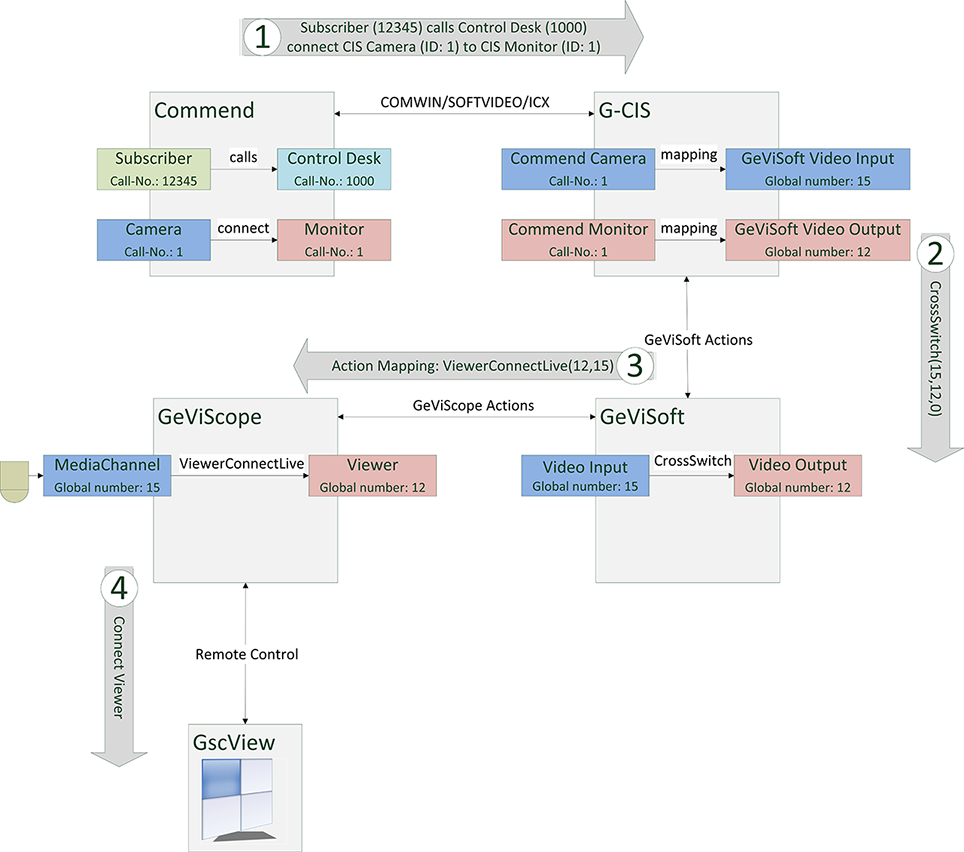
The following figure shows an overview of a G-CIS setup. If subscriber 12345 calls control desk 1000 the media channel with global number 15 connects to the viewer with the global number 12 in GSCView. The following steps are necessary to achieve the desired result:
-
Subscriber 12345 calls control desk 1000. In the COMMEND INTERNATIONAL system there is a rule, that COMMEND Camera 1 should be connected to COMMEND Monitor 1.
-
G-CIS listens on the COMMEND INTERNATIONAL system and receives the request. The COMMEND call number must not match the GeViScope global number. To map between the two systems there are two lookup tables: Camera mappings and Monitor mappings. In this setup the COMMEND Camera 1 is mapped to GeViSoft video input 15 and COMMEND Monitor 1 to GeViSoft video output 12.
-
G-CIS now generates and sends a CrossSwitch action to GeViSoft to propagate the request.
-
GeViSoft receives the request and translates the CrossSwitch action to a ViewerConnectLive action (GeViSoft: Action Mapping) and sends it to all connected GeViScopes.
-
GeViScope receives the ViewerConnectLive action and connects media channel 15 with viewer 12.