BaroxSwitchSNMP
The BaroxSwitchSNMP plugin connects a Barox switch to G-Core via SNMP. The IP switch operation action is used to operate a port of the switch.
System Requirements
The following Barox switches can be used with the BaroxSwitchSNMP plugin:
-
RY-GSP17-10 (Do not connect this switch to another switch with PoE)
-
RY-GSP22-26-370
-
RY-LGS23-26
-
RY-LGSO25-24
-
RY-LGSO25-28
-
RY-LGSP23-10G
-
RY-LGSP23-26 (No PoE)
-
RY-LGSP23-26370
-
RY-LGSP28-10
-
RY-LGSP28-52-740
-
RY-LGSPTR23-26
-
RY-LGSPTR28-52
-
RY-LGSO25-28 (No PoE)
-
RY-LPIGE-602GBTME
-
RY-LPIGE-804GBTME
-
RY-LPITE-802GBTME
-
RY-LPITE-804GBTME
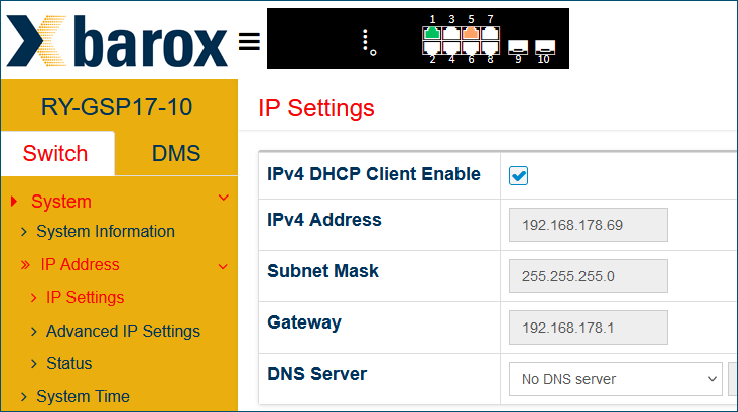
IP address:
The Barox switch must be part of the IP range of the G-Core server. By default, the switches have the IP address 192.168.1.1.
The IP address of the Barox switch can be changed on 192.168.1.1:180. The login data are:
-
Username: admin
-
Password: admin
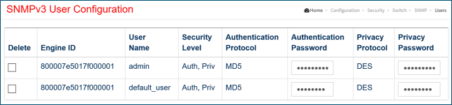
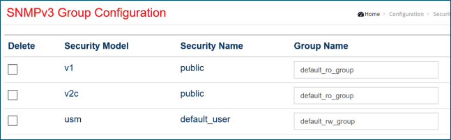
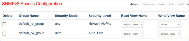
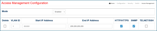
SNMP must be configured in the web interface of the Barox switch. The plugin supports SNMP versions 1, 2 and 3.
Example
Configuration for SNMPv3 with the username default_user: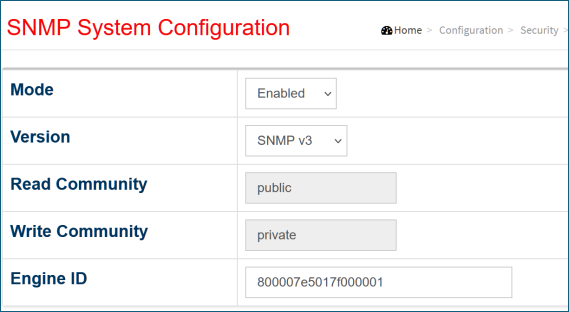
Installation
How to install the plugin:
-
Run the
BaroxSwitchSNMPPlugin_installer_xxx.exefile on the G-Core server.Ensure that the BaroxSwitchSNMP plugin version and the installed G-Core version are compatible.
-
In the License Agreement dialog window, select the option I accept the agreement and click Next.
-
In the Ready to Install dialog window, click Install.
-
Restart the G-Core server.
The plugin files (BaroxSwitchDeviceSNMP.dll, BaroxSwitchSNMP.dll and BaroxSwitchConfig.json) and the BaroxSwitchSNMPUninst folder are added to the G-Core installation directory.
Add the Plugin
How to add the BaroxSwitchSNMP plugin:
-
Click the
 icon in the toolbar of the Hardware configuration window. The Add hardware module dialog window opens.
 -
Select the Plugin <BaroxSwitchSNMP>.
-
Click Add. The plugin is added to the Hardware module list.
You must add a separate plugin for each Barox switch. You can add a maximum of 32 plugins.
Configuration
Plugin Settings
How to configure the plugin settings:
-
Select the plugin from the Hardware module list.
-
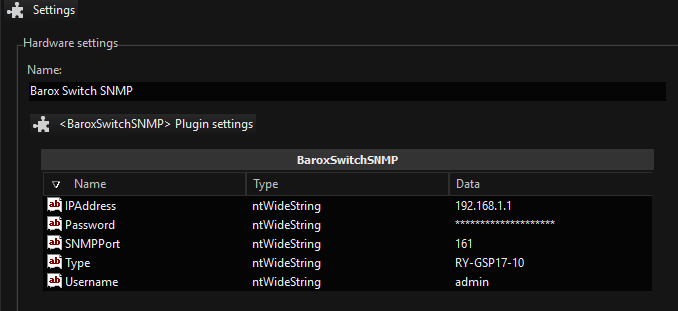
Specify the plugin settings.
The plugin supports SNMP versions 1, 2, and 3. Version 3 is set as default. Be sure to specify the SNMP version and settings used in the Barox SNMP configuration. If you are using version 1 or 2, the default values for the SNMPv3 settings can remain unchanged.
Name
Description
AuthPassword
If SNMPv3 is used, enter the authentication password of the user (default user:
default_user) used in the Barox SNMP configuration.AuthProtocol
If SNMPv3 is used, specify the authentication protocol used in the Barox SNMP configuration. It can be MD5 or SHA.
Community
Specify the community string used in the Barox SNMP configuration. If SNMPv3 is used, this setting must be set to
private.IPAddress
Enter the IP address of the Barox switch. The default IP address is
192.168.1.1.PrivPassword
If SNMPv3 is used, enter the privacy password for the user (default user:
default_userused in the Barox SNMP configuration.PrivProtocol
If SNMPv3 is used, specify the used privacy protocol used in the Barox SNMP configuration. It can be DES or AES.
SNMP Version
Specify the SNMP version used in the Barox SNMP configuration. It can be version 1, 2 or 3.
SNMPPort
Enter the SNMP port of the Barox switch. The default port is 161.
Type
Enter the model type of the Barox switch (see Usable switches).
Username
If SNMPv3 is used, enter the user name used in the Barox SNMP configuration.
-
Click the
 icon in the menu bar to save your configuration.
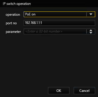
IP Switch Operation Action
To operate a port of the switch, use the IP switch operation action. It allows you to turn specific PoE ports of the switch on or off to restart connected cameras. The switch can also be rebooted via the plugin to interrupt the PoE power supply to all connected devices. You can also disconnect specific switch ports from the internet by disabling them.
How to configure the IP switch operation action:
-
Add an event with the IP switch operation action to the media channel of the plugin.
-
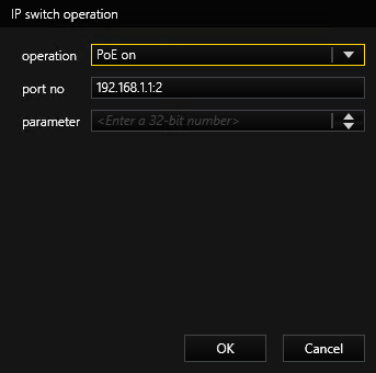
In the operation drop-down list, select the operation you want to do. The following operations are available:
Operation
Values
PoE on (0)
Power on PoE, port number 1
operation: PoE on (0)
port no: <IP Address>:1
Power on PoE, port number 2
operation: PoE on (0)
port no: <IP Address>:2
Power off (1)
Power off PoE, port number 1
operation: PoE off (1)
port no: <IP Address>:1

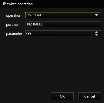
PoE reset (2)
Reboot Barox switch, port number 1
operation: PoE reset (2)
port no: <IP Address>:1
parameter: -99
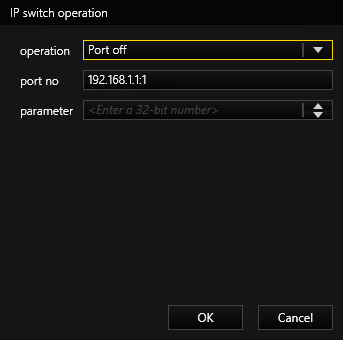
Port off (4)
Disable port number 1
operation: Port off (4)
port no: <IP Address>:1
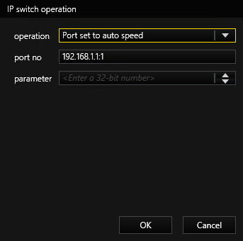
Port set to auto speed (5)
Set auto speed, port number 1
operation: Port set to auto speed (5)
port no: <IP Address>:1
-
In the port no field, enter the IP address and the port number of the switch (
<IP address>:<port>). -
Click the
icon in the menu bar to save your configuration. -
The plugin retrieves the required SNMP command from the switch.