Understanding and Using VMD
Comments on the Function of the VMD
When you open the VMD window, you will already see 4 chains with 8 zones each. These 32 zones make up the base frame for the VMD.
Although you can add a maximum of 96 additional zones (individually or as chains), until the maximum of 128 zones has been reached, it is not possible to have less than 32 zones.
The reason for the limitation lies in the fact that, for steady and reliable measurement for distinguishing between global and local changes in the picture, a minimum number of zones must be evaluated.
If, however, you require fewer than these 32 zones for your specific circumstances, set the remaining zones to 'Suppression'.
If you have set zones to Suppression, these zones are subsequently only used for the calculation of global changes. These zones should not be situated on parts of the picture that contain movement (trees, bushes, clouds, flags etc.) and also not on segments with fluctuations in contrast (the sky in general, bright car headlamps, flashing advertising, etc.). Including these kinds of zones will lead to sensors becoming less sensitive.
How does this work? The suppressed part (indicated by a percentage) is subtracted from all the measured global changes in the picture. Given that both the movement and the contrast threshold have been set correctly, with a suppression threshold of 100% neither a global nor a local change will be signaled. With a suppression of 0%, there will be constant movement detection, where any change in the picture will always be signaled.
Based on the above-mentioned conditions (moving sections of the picture or strong changes in contrast), it is essential to monitor suppression at various times of the day and with various light/weather ratios. Anyone who has seen a lawn at different times of day will understand how tricky it can be to correctly set the suppression: In the morning with dew and back-lighting, the lawn shines like silver (high white value), while in the afternoon it is a soft green (mid-greybeard value). Or, something that is often not taken into consideration: Plants grow and change with the seasons. Moving shoots push into the picture, and where vision was clear in autumn, shimmering foliage fills the picture in summer.
Via actions and/or the configured time ranges, it is possible to start adjusted profiles for the VMD at various times of day. In this way, difficult situations can be better managed.
Alarm Configuration
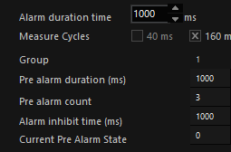
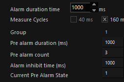
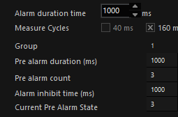
The alarm configuration displays all the important settings in a clear, tabular form.
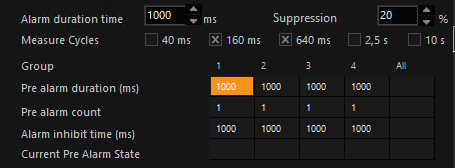
The alarm duration time in milliseconds must first be set. This setting applies to all alarms.
It is possible here to make settings for each group or one for all the groups in the All column.
Pre-Alarm Time
Special attention should be paid to the Pre-alarm duration; in our example we have entered 1000s.
The pre-alarm duration is the length of time within which the number of pre-alarm zones entered under the Pre-alarm count must detect movement before an alarm is recognized. (See below)
This is considered in more detail below. The Alarm inhibit time line specifies the time for which all the alarms in all the groups are inhibited once a movement has been detected in an inhibit zone.
Measurement Cycles and Image Contrast
In the alarm configuration settings area you will also find a line called Measurement cycles, where five settings are possible.

The activated measurement cycles are also displayed as curves on the monitor. The values for 40 and 160 ms are:
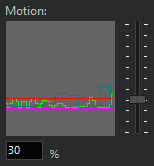
These times require explanation:
Example Let us consider an alarm zone with a measuring cycle of 40 ms. This means that contrast changes within the zone will be compared every 40 ms. If a ball now flies through the zone it will be detected, since 40 ms is quite short. If, however, a person slowly and carefully creeps through the zone, the contrast changes occurring within 40 ms are too small to trigger an alarm.
On the other hand, the situation with a setting of 10 s is the reverse: The ball will not be detected, but the slowly creeping person will be.
This is, however, only true when the size of the objects has a reasonable relationship to the size of the zone. As shown here, with our example figure.
Nevertheless, a smaller object such as a rabbit could also be detected, provided the contrast is strong enough. If the contrast is too weak, detection will not take place.
|
|
|
|
Is recognized |
Is not recognized |
This gives us three criteria for setting the measuring cycles: speed, size and contrast. To make the right settings, you should:
- Make your settings in monochrome mode, so that it is easier to judge the contrast
- Test various measuring cycles and their combinations
- Deliberately initiate alarms using people and/or objects under different light conditions and with varying contrasts
- Pay particular attention to the settings for dusk and night (zones in totally dark areas are as useless as zones in which the camera image is flooded by searchlights).
Seasonal conditions (a low sun, white areas of snow, etc.) should also be considered.
Alarm and Inhibit Zones
Alarm Zones
Alarm zones are appropriate in those parts of the image where movements are to be detected. Single zones (chains with a single link) or full chains may be used. A chain is particularly useful when, in addition to the movement itself, the direction and speed are also to be detected. Pre-alarm zones are particularly helpful here (see next section).
Inhibit Zones
The case of inhibit zones is different: Because inhibit zones do not trigger an alarm in response to activity, but inhibit triggering of the alarm by the alarm zones for a specified period of time, they are only used in special cases.
If you have created inhibit zones, and if a movement is detected in these inhibit zones, all the alarms in all the groups will be inhibited!
From Pre-Alarm to VMD Alarm
In this section we want to use an example to explain the way pre-alarm zones function. We have created a very simple scenario for this purpose:
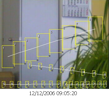
In the next illustration, you see a pre-alarm chain having 10 zones that has been created in area 1.
|
|
The pre-alarm count has been set to 3, which means that if 3 zones in the chain are activated by movement within the 1000 ms pre-alarm duration, a VMD alarm will be initiated. The Current pre-alarm state shows how many zones satisfy the above condition. |
|
|
The VMD alarm LED is not showing an alarm. |

In the next illustration, our example figure triggers a movement signal in zone 10 of the chain. The detection zone is outlined in cyan, because it is the zone with the maximum detection level.
|
|
You can see, under Current pre-alarm state, how the movement in zone 10 causes a change in the status (from 0 to 1). |
|
|
The VMD alarm LED is not showing an alarm. |
Our figure moves on: Zone 10 is now outlined in dark red, which shows that it is in the pre-alarm state. Zone 9 is cyan, due to the maximum movement detection.
|
|
The Current pre-alarm state jumps from 1 to 2, since by now 2 zones in the pre-alarm chain have come to satisfy the condition. |
|
|
The VMD alarm LED is not showing an alarm. |

Our figure has triggered a movement detection in zone 8 within the specified time. Zones 10 and 9 are in the pre-alarm state, and the current zone 8 also triggers.
|
|
The counter now rises to 3. |
|
|
The VMD alarm LED also shows an alarm. |

The Significance of the Perspective
People, of course, appear smaller when at greater distances than when they are close to the camera. They also move at correspondingly different speeds on the monitor screen.
Our example figure illustrates the perspective problem. The change in size can clearly be seen.
Nevertheless, a motion detector should be able to record all movements with the same degree of reliability, irrespective of their size and speed on the monitor.
Further above we have seen how chains are formed and can be shaped. Due to the way in which the detection zone size and the distance of the detection zones from one another can be adapted to the perspective of the objects (or persons) to be detected, the VMD system is well able to satisfy the demand for consistent movement detection.
Exporting Viewer Snapshot
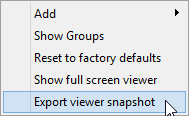
You can export the installed chains as a snapshot in order to record these settings.
If you would like to export the installed chain as a snapshot, double-click on the viewer and, in the menu, on Export viewer snapshot.
A dialogue box opens in which you can specify the name for the snapshot and the file location where it is to be saved:
By clicking on Save, the options dialogue box for the image for exporting will open:
After having specified the font and the arrangement of the lettering, click on OK. A snapshot of your alarm/restriction zones is saved.