Map Objects
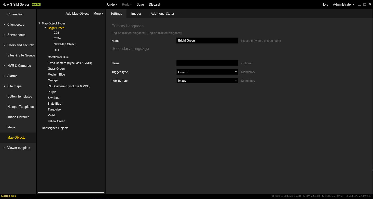
The menu has a tree view with the following structure:
-
Top-level nodes: Map Object Types (contains existing map object types) and Unassigned Objects (contains map objects that have been added to the map but not assigned to a specific type).
-
Map Object Type nodes: These nodes represent map object types, and each has map objects as child nodes.
-
Map Object nodes: These nodes are instances of map objects types and represent map objects that were added to the map.
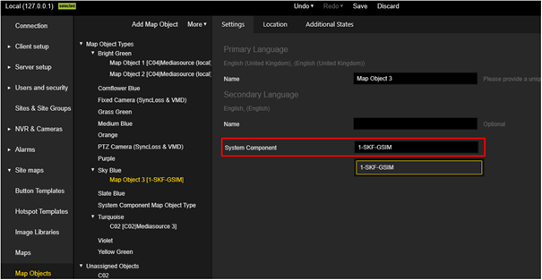
Map objects from third-party systems contain the system name in blue letters (see G-Connect).
Settings
The Settings tab allows the user to specify the Name (for primary and secondary language), Trigger Type and Display Type.
You can define the description of a button in two places. In the Settings tab, if you have selected the option Button as Display Type. In the Additional States tab, if you have selected the option Button in the Configure Image or Button area.
If you have defined the description of the button in both places, the description you have defined in the Settings tab will be overlapped by the description in the Additional States tab.
Therefore, be sure to define the description of the button in only one place.
Alarm Logic
To limit alarms by displaying them only on specific RemCons, alarm templates / instances for the specific ReCons can be restricted in the Management Console Restriction view.
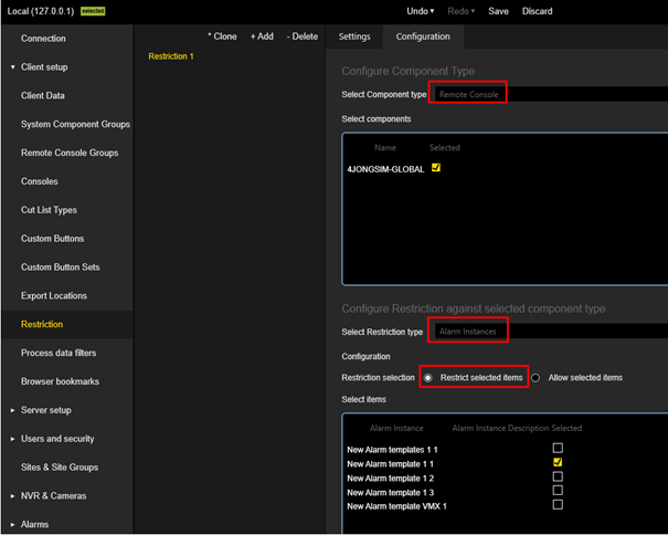
Navigate into the restrictions Configuration tab.
As Component type select Remote Console. Select the Remote Console which should be restricted in the section below.
Than select for Select Restriction type Alarm Instances.
The appropriate radio button on the Restriction Selection group chooses to restrict or allow items .
If Restrict selected items is selected, the alarm templates / instances selected below will be hidden.
If Allow selected items is selected, the alarm templates / instances selected below will be shown.
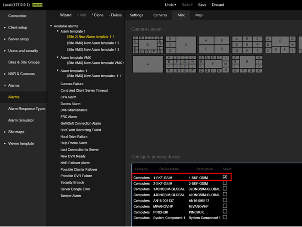
Primary Device
Primary Devices can be used to create Map Objects with the system component Trigger Type. If an Alarm with primary device is triggered, then all Map Objects with the System Component Trigger Type that are linked to this device will be entered in Alert-On state. So they will flash on the map.
A Primary Device can be added to alarm template / instances in the Management Console via the Misc Tab. By selecting a device in the Configure primary devicebox the device will be added to the alarm template / instance as primary device.
For each Map Object Type a trigger can be selected that determines when Map Objects belonging to this Map Object Type switch to alarm mode.
In the Settings tab of the Map Object Type select the Trigger Type System Component.
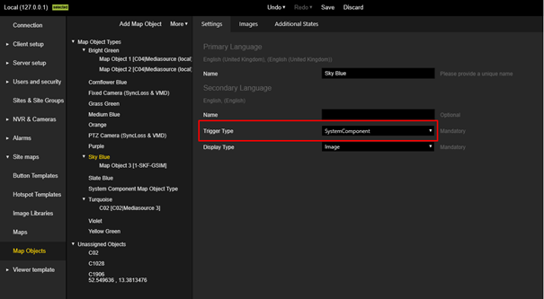
In the Settings Tab of the Map Object itself select as System Component the primary device.
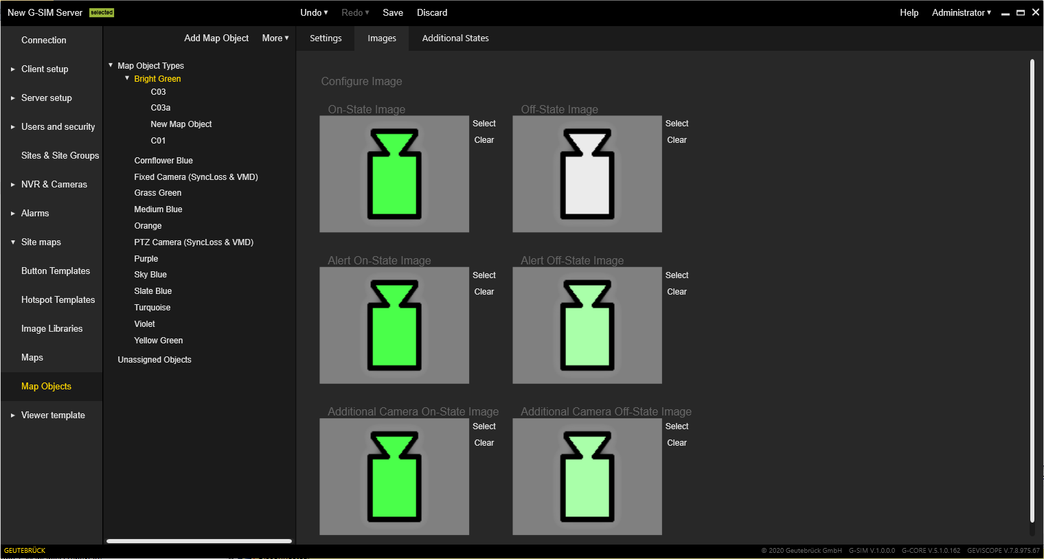
Images
The Images tab allows the user to set images of map objects of the selected type for different states:
-
On
-
Off
-
Alert On
-
Alert Off
-
Additional Camera On
-
Additional Camera Off
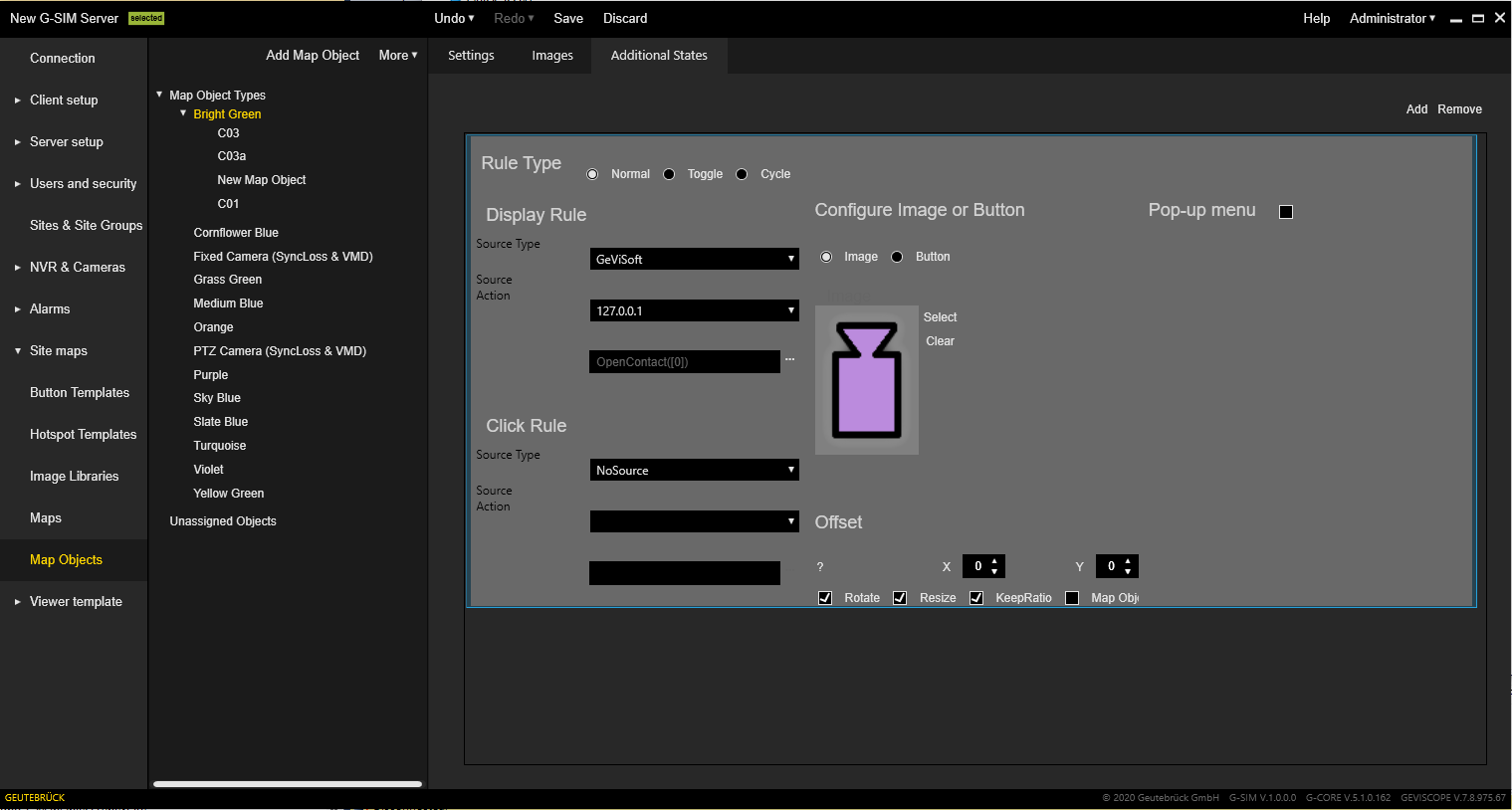
Additional States
The Additional States tab allows the user to configure additional states for map object types.
Additional states can be added or removed using the Add or Remove buttons in the upper right corner.
The Additional State tab consists of six areas:
-
Rule Type
-
Display Rule
-
Click Rule
-
Configure Image or Button
-
Pop-up menu
-
Offset
You can define the description of a button in two places. In the Settings tab, if you have selected the option Button as Display Type. In the Additional States tab, if you have selected the option Button in the Configure Image or Button area.
If you have defined the description of the button in both places, the description you have defined in the Settings tab will be overlapped by the description in the Additional States tab.
Therefore, be sure to define the description of the button in only one place.
Rule Type
There are three rule types for additional states: Normal, Toggle and Cycle.
Select a rule type depending on the intended use and what type of source is used for the state changes.
Display Rule
The Display Rule area contains the following settings:
|
Settings |
Description |
|---|---|
|
Source Type |
The source type for a display rule depends on the rule type. The following source types are available:
The rule type Toggle cannot have Alarm Type as source. |
|
Source / Action |
Depending on the selected source type, the Source drop-down field lists the possible sources and the Action drop-down field lists the corresponding actions. |
Click Rule
The Click Rule area contains the following settings:
|
Settings |
Description |
|---|---|
|
Source Type |
The source type for a click rule depends on the rule type. The following source types are available:
The rule type Toggle cannot have Alarm Type as source. |
|
Source / Action |
Depending on the selected source type, the Source drop-down field lists the possible sources and the Action drop-down field lists the corresponding actions. |
Pop-Up Menu
When you have specified a click rule, you can define an additional pop-up menu that explains what the click rule does. To do this, select the checkbox Pop-up menu.
This pop-up menu and the text defined there will be displayed when someone right-clicks on the state image.
Edit Instance Definition
Note that only the appropriate type is defined in these settings. For an actual instance to react as desired, you must go to the instance definition of the map object and edit it there (to do this, expand the type in the type list to go to the instance definition).
For example, for a toggle connected to a digital input on a DVR, you must go to the instance, select the appropriate display rule and click the action. A dialog box will appear where you must enter the relevant details such as DVR name and Digital Input number.
Camera-Linked States
Additional states can be linked to a camera (e.g. video synchronisation failed). Currently, BlockingFilter is the only action where you can choose whether to link to a camera.
In camera-linked states, the source (DVR) and the global channel number of the camera are extracted from the camera - no parameters need to be filled in. This is also the case with BlockingFilter, where Connect Camera is selected.
In the case of the selected BlockingFilters action connected to the camera, the filter is appended with the camera channel number. If the definition is BlockingFilterDeactivate("[DISARM_[cam]]]), the instance for camera 303 in its display rule will be BlockingFilterDeactivate("DISARM_303").
Note that the text [cam] is automatically generated when [link camera] is selected. The correct event name on the DVR is DISARM_303.
This is another example that demonstrates why it is important to complete your DVR configuration and setup before starting configuration in G-SIM.
The parameters of actions that are not camera linked are not automatically filled in, even if some of the actions for the map object type are camera linked.
For example, if a video synchronisation failed and you set the digital output, the parameters for the failed synchronisation are extracted from the camera, but you need to set the parameters for the digital output.
Parameters
Parameters used in the map object type template are used as variables: If you have a digital input(0) and a digital output(0) set, this means that you want to use the same contact number for both the input and the output. You also have the option to specify only one contact ID.
Use two different numbers in the template if you want them to be different in implementation.
The number can be any number. If it is a "global" contact that should be the same for all implementations, specify the correct contact ID from the beginning. It is used as the default ID in the implementation and is correct for all implementations of this card object type.
The same applies to the source of the additional states, as described above for simple parameters. The source selected in the template is used as a variable in the implementations. If all actions have the same source, select the same source for all in the template. If you want the source for implementations to be the same, select the correct source in the template as it is used as the default.
You can provide your own images or choose from our large image archive (library).
Offset
Once you have selected an image, you can use the X and Y offset values to move it away from the associated map object image (by default it is located in the centre of the image and at the top of the image). In relation to the linked object image, you can also allow rotation (Rotate), resizing (Resize) and ratio behavior when resizing (KeepRatio).
When the Map Object check box is selected, the selected click rule is triggered when the operator clicks on the image of the associated map object. This is useful if the state image is very small and difficult to click on, or if a particular action is required when the map object itself is clicked on.